|
Here is the detail description of the [ESA] Electronic Spark Advance Controller (sometimes called the Spark Controller) functional components as well as the pinouts for the two electrical connectors.
This FAQ can be helpful when trying to determine if the spark controller or any of it's functional components, external wiring or sub systems (like sensors) may be causing a drivability or no-start condition.
The Engine computers (spark computer, ESA module, etc.) on the 2bbl Chrysler 2.2 is basically a higher tech version of the "lean burn" system they introduced in the '70s. It has several proprietary RCA chips inside which are sealed in epoxy to keep out moisture.
The computer monitors the following items: (TBI & turbo engines have more sensors but are similar in operation)
Oxygen Sensor-This is located in the exhaust manifold, it's how the computer measures air/fuel ratio and what it uses to determine the fuel curve. It gives out a 0-1 volt signal, where 0 is maximum lean and 1 is maximum rich.
Coolant Temp Sender-On the side of the "water box" it tells the computer the water temperature. It should read between 5000-6000 ohms between the two pins at room temp
Vacuum Transducer-On top of the ESA module. This is where the computer measures engine vacuum and thus determines spark advance. It's basically like mounting the vacuum advance module on the computer instead of on the distributor like on older cars. This was replaced with the MAP sensor on TBI & turbo models.
Hall-Effect Pickup-Inside the distributor cap. The computer uses this to determine when the spark plugs should fire and is also how it senses engine RPM.
Carb. Switch-On the end of the idle stop. This lets the computer know if the engine's at idle or not.
Knock Sensor-Shelby & HO models only. Located on the transmission side of the intake manifold. Tells the computer when spark knock occurs.
The computer has control over the following:
Negative Coil Terminal-This goes right to the computer and is how the computer controls spark timing, thus eliminating the old "points" style system.
Feedback Solenoid-On top of the carburetor. It replaces the traditional "power valve" and is how the computer controls fuel delivery to achieve optimum air/fuel ratio.
Vacuum Secondary Solenoid-On top of the carb. The computer uses this to bleed out vacuum from the vacuum secondary diaphragm and keep the secondary throttle plate from opening until the engine has warmed up.
Canister Purge Solenoid-the passenger side of the engine compartment -when this is energized pressure from the air-pump is injected through a hose and into the emissions canister. This forces fuel vapors out of the canister and into the intake.
Solenoid Kicker-On the back of the carb. When engaged the solenoid presses on the throttle and increases engine idle. Right when the engine shuts off, the solenoid disengages and backs off of the throttle to prevent engine after run.
Solenoid Kicker Vac Solenoid-Next to the canister purge solenoid. This is how the computer controls the solenoid kicker. When it's energized, it ports manifold vacuum to the solenoid kicker on the carb, and extends it to increase engine idle. When you press the accelerator and then back off, the solenoid should keep the car at higher then normal idle for 2 seconds and then let go. It should also turn on whenever the A/C is activated (on cars so equipped)
Upshift light-Manual trans only. Located on the dashboard. Lights up at certain RPM/vacuum points. (auto trans models are simply missing the bulb in the dash)
Radiator fan relay-On the drivers side shock tower. Turns on the fan when a specified coolant temp is reached. (some '83 & older cars use a seperate switch for the fan that is not computer controlled)
Spark advance is determined by three factors:
Coolant Temperature-The temperature of engine coolant determines which vacuum advance schedule the computer will use.
Engine Vacuum-The computer has different vacuum advance schedules built into it that correspond to different temperatures.
Engine Speed-As the engine increases in RPM so does the spark advance (similar to the centrifugal advance built in to many older distributors except it's electronically controlled). Advance due to speed is disabled when the engine is using the cold advance schedule.
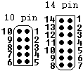
These are the carb computer's pin-outs for 1985-1987 computers. (1984 & earlier computers have different pin-outs) Some of the older 2bbl spark modules have a 10pin and a 12pin connector while others have a 10pin and a 14pin, very early ones only have one 10pin connector.
-
The 10-pin Connector pins:
- Negative ignition coil terminal
- 12VDC (in from ignition switch)
- 12VDC (out to hall effect pickup)
- Not Used
- Hall Effect Pickup
- Knock Sensor Input (HO engines)
- Carb Switch
- To Radiator Fan Relay
- Ground
- Ground
- The 14-pin connector pins:
- Vacuum Secondary Solenoid
- Temp Sender
- Oxygen Sensor Input
- Temp Sender
- Mixture Solenoid Control
- Purge Solenoid
- To Diagnostic Connector
- 12VDC
- Purge Solenoid
- 12VDC
- Tachometer Output
- Upshift Light (Fuel Pacer Light)
- Distance Sensor Input (if equipped w/cruise control)
- To Diagnostic Connector
|