|
Had to replace the micro switches in my 86 Turbo Z with digital dash today so I thought that I would snap a few pics and create a FAQ on how this is done. It is a straight forward operation that is not difficult as long as you know how to solder small electronic components and have the appropriate electronic de-solder/soldering tools. The small micro switches used in the digital dash are also used in the (Traveler) and 12 button Navigator systems. If you are not sure if you are good at soldering electronic components, well then you aren't. In that case this is a task best left to someone who is and that has the proper tools. The switches are delicate, the PCB board is easily ruined with a soldering tool that is too big or too hot, and removing the old switches really does require either a de-soldering tool or some de-soldering wick.
OK, here is what you will need to accomplish this task:
1 small tip electronic soldering pencil (or small tip micro torch)
1 de-soldering tool (bulb sucker type, heated tip type w/bulb, or very fine de-solder wick) I suggest the heated tip type with bulb
1 small amount of electronic solder (this will be fine, electronic solder with a rosin core) Do NOT use acid core solder
3 replacement mico switches (Mouser Electronics # 113-DTST-65N-V or Diptronics #DTST-65N-V)
8 #74 micro lamps to replace the ones in the cluster since you are already going to have it apart (optional)
5 #194 lamps to replace the ones in the cluster since you are already going to have it apart (optional)
Step 1: Remove and prepare the digital dash cluster
Start by removing the cluster from the dash. This is typically going to require only removal of the cluster bezel which is held in place across the top by several Philips head screws and across the bottom by some clips that just snap in and out. Don't pull too hard on the bottom of the bezel to get the clips to release, pull with even force, gently and straight out, it should snap out fairly easily.
Remove the cluster from the dash by removing the 4 Phillips head screws attaching it to the dash shell. Once the screws are removed, you will need to reach behind the cluster to disconnect the three(3) electrical connectors. All three of them have a locking tab that has to be raised for the connector to slip out.
Placing the tilt steering wheel down as far as it will go may help you get the cluster out more easily.
Once the cluster is in hand, remove the (3 or 4) 194 lamps that are on the left side of the cluster. The left side as if it were still installed in the dash. Then remove the faceplate by removing the Phillips head screws that hold it on the cluster assembly. Then remove the small bolts that hold the cluster module inside the cluster assembly. At this point you can slide the cluster module out of the cluster assembly. Take care to glide and slide the flexible conductor ribbon where the three 194 bulbs were installed out carefully.
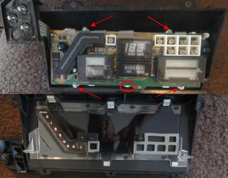
With the cluster module in hand, you need to release the upper module from the lower module by pushing down on the white plastic lock that holds the modules together. The lock is in the middle of the module as shown in the picture below.

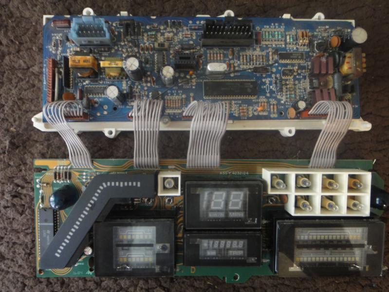
Once you have released the module board lock they can be seperated and you should then have a pair of digital cluster boards that look like this:

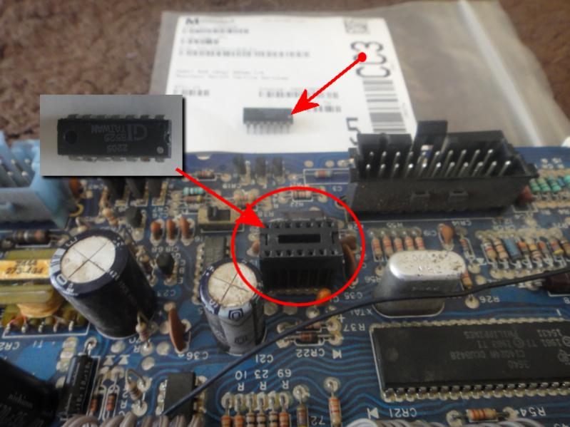
If you are curious about the odometer chip. It is the only chip on the module that is not soldered in place. In the picture below, you can see the chip has been removed, it is pictured in the background as well as in the inset for better visibility. Note the position of the white dot!

Step 2: Locate and remove the three micro switches
Now that you have the cluster apart, you can easily see the three switches that need to be replaced. And on the back of the board, you need to find the solder pads that are holding the switches in place. Below are two pictures, the first pictures shows you the location of the top side of the switches. That's easy to see. The bottom side, is just a little bit trickier. You need to be sure to locate the exact solder pads that are holding in the switches, not some other component!
Here are close up pictures of the bottom of the PCB to help you locate the correct solder pads for the micro switches.
Using an appropriate de-soldering tool, remove the three switches. Take care to not overheat the PCB with the de-soldering tool or to de-solder the wrong pad!
Here is a picture of the three old and three replacement switches. They do not look the same but the new pieces from Mouser are a perfect fit.
Step 3: Solder in the new switches
After you have removed the old switches, insert the new switches and pull them snugly against the PCB. This is VERY important that they be flush with the board and properly aligned with the holes in the PCB. It's just a matter of a little tug on the legs to get the switch flush with the PCB, then just push the switch legs one to the left and one to the right to hold it well in place while you apply a small amount of heat to the pad and leg simultaneously and apply the electronic solder. Just a small bit will do the trick.
Step 4: Reassemble the cluster
...by reversing the steps above and reinstall the cluster in the dash.
Optionally, you can replace the #74 and #194 lamps while you have the cluster disassembled. The #74 bulbs just pull straight out of the socket. The #194 lamps also pull straigh out of their socket once you remove the socket from the PCB with a 1/4 twist.
It's a good tip to clean the flexible conductor that the #194 bulbs twist lock into. A pink pearl pencil eraser works very well for this. Otherwise choose a very fine steel wool (like 000 or 0000) to clean the surface before installing the bulb with its base. If you use steel wool, BE SURE to blow out any residue that might accumulate on the PCB boards. Steel wool is ..well made of steel...which conducts electricity and you don't want ANY of that stuff shorting out arbitrary components in your digital dash cluster.
|