|
I just went through the front end of my 89 CSX and I thought I would share some of my key learnings from this exercise. I was experiencing a few creaks and moans on bumps and slow turns and knowing the cars suspension bushings and related hardware had 170K+ miles, I assumed it was probably time for replacement.
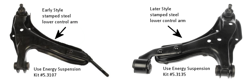
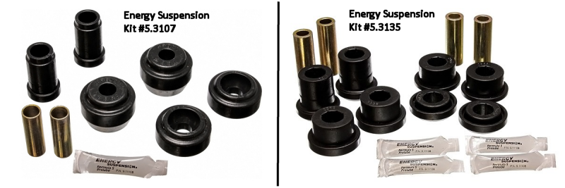
NOTE: If you check the application chart for 1989 Dodge Shadow using the Energy Suspension catalog feature, as well as many online auto parts stores, they will probably indicate to you that you need kit #5.3107 WHICH IS WRONG. The kit #5.3107 is for the early style control arm. The 89 CSX actually has the later style stamped lower control arm, which is different than the cast aluminum which comes on the later cars.
The correct kit for the 89 CSX and any other turbo Dodge car that does not have the early style stamped arm, nor the later style cast aluminum arm is #5.3135.
Here are two pics of the early and later stamped control arms. The early one is on the left the later one is on the right.

Here are two pics of the early and later stamped control arm replacement bushings from Energy Suspension. The early ones are on the left the later style are on the right.

Here are the steps for replacing the bushings:
1. Raise the front of the car with a suitable floor jack and then support the car appropriately on both sides with a good quality jack stand. Be certain that the stands are well placed and that the car is on level and firm ground. Jack stands on dirt are dangerous. Safety is very important!
2. Then loosen and remove the front sway bar bracket bolt that is attached to the control arm, then loosen the rear bolt enough to be able to push the bracket out of the way of the sway bar. Do the same on the other side of the car and then push the sway bar down and out of the way, far enough to be able to remove the control arms in the next step.
3. Remove the lower control arm. On the early style you have to remove the rear strut rod nut that is inside the sub-frame/cross member then the front nut and bolt from the front of the arm. Then loosen and remove the bolt and nut that holds the control arm to the ball joint. On the later style, you remove the front and rear control arm bushing bolts, then the ball joint nut and bolts. Once the bolts have been removed, the control arm can be pulled out and away from the car.
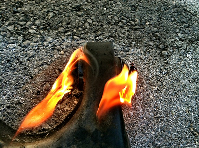
4. Using heat, like from a butane torch or a shop torch, heat the metal portion of the control arm around the bushing. Try to evenly distribute the heat so that you get all the metal around the bushing hot enough to break the bond of the rubber to the metal. Once the metal around the bushing is hot enough it will begin to smoke and it can be easily pushed out with something like a large screw driver. It is not necessary to get it so hot that the rubber catches fire, but if it does, you'll know you are getting close to hot enough. At some point the bushing will practically fall out on its own if you get it hot enough and/or it catches fire. I like to do this over a bucket of water so that when the bushing falls or is pushed out, it falls into the bucket of water. This avoids a lot of smoking rubber stink and may avoid a shop fire if there are flames present. As soon as the bushing is out I drench the part in the cool water, this helps to prevent making the metal soft from the heat of the torch.

(If you are fortunate enough to actually have the Chrysler control arm bushing tool to remove and install them, then use that tool. I do not describe that process here)
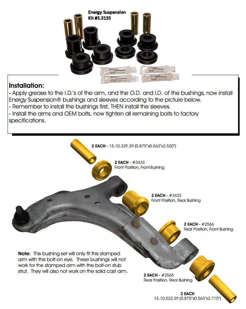
5. Grease the inside of the bushing eye socket with the included silicone grease from the Energy Suspension bushing kit. Install the bushings on the later style stamped lower control arm as illustrated in the diagram below.

6. Once the bushings are installed and properly greased, reinstall the control arms reversing the steps in step #3. It might be a good idea to brush some anti-sieze compound on the bolt shaft and threads to keep it from potentially seizing to the new metal sleeve inside the bushing.
7. Replace the front sway bar bushings in reverse order from step #2
|