HOW TO INSTALL AN EXTERNAL VOLTAGE REGULATOR IN YOUR TURBO DODGE
This how to guide shows how to install an external voltage regulator in a turbo Dodge car from 84-87 and would be applicable for Chrysler, Dodge and Plymouth cars such as Omni (GLH & GLHS),Shelby Charger, Horizon, Daytona, Laser, Lebaron, Spirit, Caravelle, New Yorker, Caravan and other similar vehicles equipped with separate logic modules and power modules.
The Problem With Voltage Regulators built into the Power Module:
These “k-car” era automobiles use an electrical charging system that incorporate the voltage regulator that balances the need for charging the battery inside the power module. The voltage regulator is controlled by a single wire connection from the logic module. So it is a power module/logic module dependent system.
The logic module and power module are not typically owner serviceable and if the voltage regulator in the power module either fails in the full charge mode or no charge at all mode, it is not replaceable. So when you have charging problems and the voltage regulator is at fault, replacing the entire power module is often necessary.
Common Symptoms:
Alternator not charging (output below 12.8v volts) or alternator over charging (output 14.7+ volts). When the voltage regulator (VR) fails, in most cases it will fail “open” (no charge) but it can fail “closed” and cause an overcharge condition.
Check These Items First:
Before blaming the voltage regulator however, it is important to do a proper diagnostics first! A complete basic troubleshooting guide is available here: http://minimopar.knizefamily.net/charging.html#charging.
Before you rush ahead and replace the power module, or install an external voltage regulator, it is a good idea to confirm that you have a good solid connection between the logic module and the power module. If this wire is open or shorted to ground, it will cause the voltage regulator to either full charge or no charge depending on whether it is shorted or open.
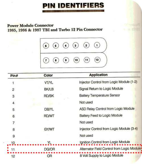
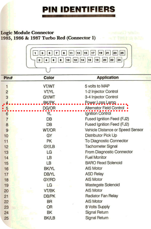
For most the cars, the red connector of the logic module PIN 5 and the 12 pin connector of the power module pin 11 are the two pins that the alternator control wires are connected to. The wire in question is a Dark Green/Orange wire typically.
The Voltage Regulator is a Known Common Failure Point
Your voltage regulator is located in your power module (PM, computer next to battery) in your 84-87 Dodge. This built in voltage regulator seems to be failure prone, and renders an otherwise good power module useless.
The Solution:
- One solution is to simply replace the power module with a good used (getting harder to find these days) or a re-manufactured unit. This solution is good and easy but it will also be prone to the same failure in the future. Many ‘good used’ power modules sitting on the shelf are on the shelf because they have an intermittent or dead voltage regulator!
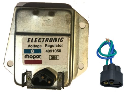
- Use an old school Mopar electronic external voltage regulator to control your alternator output! These regulators were used for decades on older Mopars, and are very very reliable. Any voltage regulator from a 70’s or 80’s truck or RWD car will work. Do not select one that is intended for use on a 69 or earlier vehicle, they are electronically different. The original style Mopar voltage regulator is typically less than $20 new, and nearly free used. There are numerous regulators from different makes that will work, I used a Mopar one because that is what I had. By tapping in to the existing wiring, we will maintain the use of our factory volt gauge. It will also allow for easy switching back to an internal regulator should you happen to find a working PM.
 |
Parts List:
- Mopar 1970-1984 Voltage Regulator (Do not use 69 and earlier)
- Plug with pigtails for regulator
- 3 x 18” 16awg wires (preferably green, blue and black)
- 2 x crimp on or solder on STEEL or BRASS eyelet connectors
- Electrical tape/ shrink tube
- Electrical Solder (rosin core or silver solder)
- Zip Ties
- Wire sheathing/loom covering
- 2 self-tapping sheet metal screws
Tools:
- Drill & 1/8” bit
- Screwdriver
- Soldering Iron
- Volt meter
- Wire stripper/knife
- Crimping tool
- Wire Cutters
- Pin-out diagram as found in Service Manual
Procedure:
- Place voltage regulator on either the inside inner fender or perhaps a shock tower. Mark and drill holes for secure mounting and to make a strong electrical ground connection.
- Solder the blue and green wires to the blue and green leads on the VR plug. If your wire colors don’t match, don’t worry.
- Note that the case of the external voltage regulator provides the ground for the circuit. It is important that when you mount the regulator, the case is very well grounded to the chassis.
- Screw voltage regulator to a suitable good chassis ground point like the inner fender or shock tower.
- Optional: Connect black wire w/loop to one mounting screw. Good grounds are very very important here.
- Plug in the pig tail.
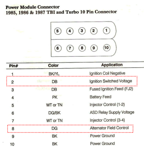
- Examine the 10 pin plug on your power module. Locate the Dark Green wire, this should be pin 8, also known as (R3). You are going to connect the green wire from your voltage regulator here.
- Locate the J2 (key on hot) circuit on the same connector. This should be pin 2 and is typically a heavy dark blue wire. Confirm 12v at key on at this pin.
- Disconnect battery
- Unplug the 10 pin plug on your power module.
- Strip 1/2”-3/4” of insulation off each of the three wires you just identified.
- Solder the green wire from the VR to the green field wire connected to pin 8 (R3)
- Solder the blue wire from the VR to the blue (“J2” switched 12v)
- Optional: Connect the black ground wire from the case of the voltage regulator to a good chassis ground.
- Tape connections thoroughly.
- Use the wire loom and zip ties to route and secure wiring.
- Reconnect computer and battery, start car and test for voltage.

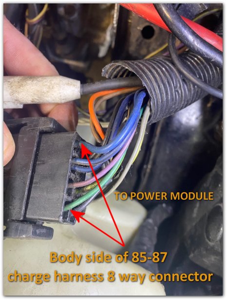
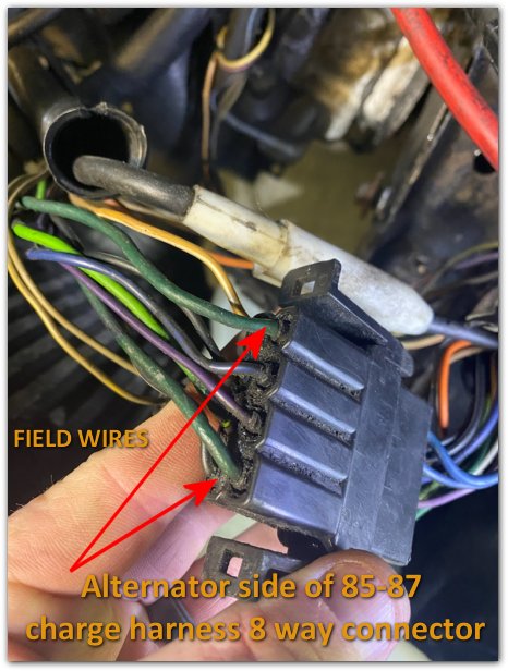
Pictures of typical 85-87 Charge Harness to Body Connector
Typical Charging System Wiring Diagrams (86 L-Body)
(CLICK TO ZOOM)
Notes:
With a working power module, your car should put out a minimum of 13.5 volts. With the external regulator, the car may put out 14.5 volts. Many external voltage regulators are adjustable. You can turn the regulator up or down but the sweet spot is going to be between 13.5 and 14.5 volts.
With a shorted closed (stuck on full charge) or a functioning power module regulator it may be necessary to cut or disconnect the field wires from the harness to the power module`, rather than simply tapping into them.
How to adjust the regulator:
An adjustable regulator grounds through it's case. To adjust the regulator voltage, run a ground wire from the voltage regulator case directly to the engine before adjusting the regulator. After you have the desired setting, unplug the harness and mount the regulator before you plug in the harness again.
|