|
Instead of buying a auto parts store rebuilt alternator for $165 (1 year warranty)or a $239 (lifetime warranty) or a new alternator for $349, I decided to simply rebuild my existing one that worked fine except for the bearings that were starting to make noise. A 'Victory Lap' rebuild kit at Amazon cost me $39 and free shipping since I have an Amazon Prime account. They normally retail for $89.
If I had the job to do over, I would have ordered good quality US or Japan made bearings in advance to install instead of the 'made in China' bearings that came with the alternator rebuild kit. None the less, it was an easy job and I saved anywhere from $130 to $310. The job took about 1.5 hours from start to finish.
Larger bearing number: 6304 2RS $6 (SKF Brand, eBay)
Small bearing number: 6202-2RS $10 (SKF Brand, eBay)
Victory Lap kit: CRA-03 (fits 90% of our cars with 90-120 amp alternator but check your application first!)
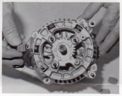
Here is an exploded view of the alternator already disassembled.

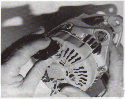
Step 1
Remove the alternator from the engine, mark each half of the housing with a marker or chisel so that they can be reassembled in exactly the same position.
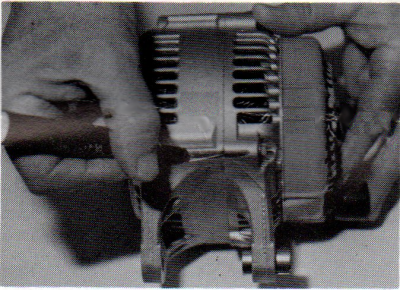
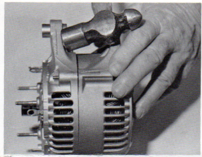
Step 2
Use a wrench and socket as shown to remove the nut from the front of the alternator. Usually it is very tight. Use wrenches with good leverage, penetrating oil, or impact tools if necessary. Remove the pulley.
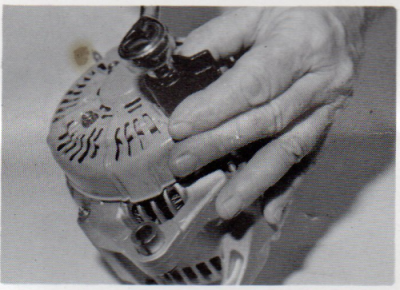
Step 3
Use a socket to remove the nut holding the battery terminal insulator. Note the position of the insulator before you remove it.
Step 4
Remove the three nuts holding the rectifier cover in place and then remove the cover.
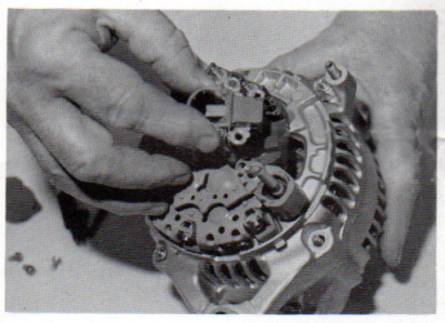
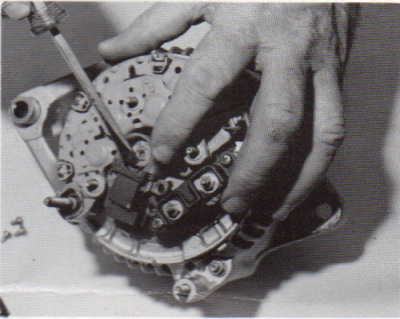
Step 5
Remove the dust cover and the 5 screws holding the brush holder assembly and the terminal block in place. Remove the brush holder assembly and then the terminal block.
Step 6
Remove the four rectifier terminal screws and remove the rectifier.

Step 7
Remove the four stator lead insulators and the four nuts holding the housing together.

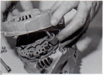
Step 8
Pry the two housing halves apart. The stator assembly stays with the front housing. Carefully remove the rotor from the housing.
Step 9
Remove the four screws holding the inner bearing retainer to the housing. Using a socket the same size as the bearing hole in the front of the housing, carefully drive the old bearing out of the housing.
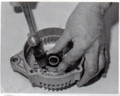
Step 10
Using a socket the same size as the outside ring of the new bearing, carefully tap the new bearing into place inside the housing. Reinstall the retainer and the four screws removed earlier.
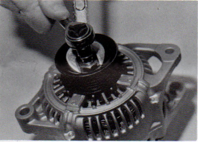
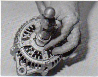
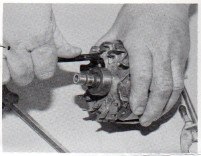
Step 11
Using two screw drivers or small pry bars, remove the smaller bearing from the rotor shaft. Take care to not damage the rotor or the two wires that are under the bearing, one on each side of the bearing.
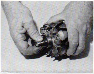
Step 12
Remove the rotor from the rear housing. Carefully clean the commutator (the part that the brushes run on) with a very fine grade of sandpaper or steel wool. When finished cleaning, be sure rotor is free of dirt, sand, and/or steel wool remnants.
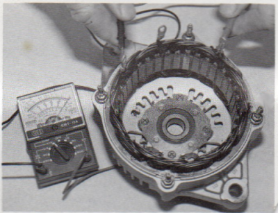
Step 13 (optional)
With an ohmmeter, it's a good idea to check the stator. First check for broken wires or loose connectors. Then test each lead with the meter to be sure that there is no resistance to any of the other leads. One at a time, pick a lead, and attach one meter probe to it, then with the other probe touch the other three, one at a time. There should be little or no resistance at all.
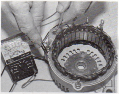
Step 14 (optional)
Now test each lead against the stator frame/housing. There should be no connection from any terminal to the frame (100% resistance)
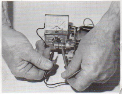
Step 15 (optional)
Now test the rotor. Place a lead on each ring of the commutator. There should be no resistance.
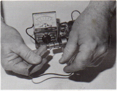
Step 16 (optional)
Now test between each ring and the rotor shaft. There should be no connection (100% resistance)
Step 17
Place the rotor in the front housing. Re-install the rear housing. Re-install the four housing nuts and tighten evenly. Replace the four stator lead insulators.
Step 18
Install the new rectifier. Re-install the four retaining screws removed earlier and tighten. Use a screwdriver or other suitable tool to compress the brushes against the springs and install the new brush holder assembly and tighten all screws. Re-install the dust cover (if present).
Step 19
Re-install the rear cover and tighten the nuts. Install the new battery post insulator in the proper position and tighten the nut after first installing the washer(s) under it.
Step 20
Re-install the nut and tighten it...tight! Re-install the alternator on the engine and reconnect the battery cable. Re-install the alternator belt, properly adjust it and then start the engine. Confirm that the alternator is charging by examining the dash volt meter or checking the voltage across the battery terminals. It should ready approximately 13-14 volts.
|