|
Turbo Dodge TI & TII 1985-1993
Throttle Position Sensor Testing Tips
The position of the throttle plate inside the throttle body is monitored by the throttle position switch, also known as the ‘TPS’ for short. It’s signal is monitored by the logic module so that it can be used for optimum engine management.
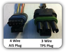
 Throttle Position Sensor (TPS) is nothing more than a simple potentiometer (a variable resistor) that reporting to the engine controller just how far open the throttle opening is. The TPS converts electrical resistance (zero to 5,000 ohms scale, ±25%) to a voltage that the computer interprets when setting engine parameters such as ignition timing, fuel mixture and idle speed. On the turbo dodge 2.2 and 2.5 engines, the TPS is mounted on the side of the throttle body, is connected internally to the end of the throttle shaft and plate. There are 3 electrical connections on its connector. The three connectors correspond to 5V, signal and ground. Throttle Position Sensor (TPS) is nothing more than a simple potentiometer (a variable resistor) that reporting to the engine controller just how far open the throttle opening is. The TPS converts electrical resistance (zero to 5,000 ohms scale, ±25%) to a voltage that the computer interprets when setting engine parameters such as ignition timing, fuel mixture and idle speed. On the turbo dodge 2.2 and 2.5 engines, the TPS is mounted on the side of the throttle body, is connected internally to the end of the throttle shaft and plate. There are 3 electrical connections on its connector. The three connectors correspond to 5V, signal and ground.
The TPS uses an indexed three pin connection. To detect the position of the throttle plate, 5 volts DC is applied to pin one, which is at one end of the potentiometer; the other end is grounded, and the wiper of the potentiometer reads the voltage resulting from the resistance that varies based on the position of the throttle.
- When the throttle is closed at or close to 10 degrees, the output voltage is between ground and the center pin is going to measure 0.2 vdc (volts DC) and 0.7 vdc.
- At Wide Open Throttle (WOT), the throttle is opened to 79 to 90° and the output voltage is between 2.6 vdc and 4.8 vdc.
- Between 10° and 79° of throttle opening (between closed and WOT) the voltage ranges between 0.2 vdc and 4.8 vdc. And the range of voltage if measured, should move slowly up and down the voltage measurement and w/o any sudden deflections of the volt meter needle.
 The minimum and maximum values are 0.2V and 4.8V, going outside of that range will typically trip a code. However, typical values are about 0.7V with throttle closed and about 3.8 to 4.0V at wide open throttle. The minimum and maximum values are 0.2V and 4.8V, going outside of that range will typically trip a code. However, typical values are about 0.7V with throttle closed and about 3.8 to 4.0V at wide open throttle.
When the logic module senses the throttle position is closed it can set the AIS motor to adjust the idle speed to the target idle speed. When it senses wide open throttle, the logic module exits closed loop and richens the fuel mixture for turbo engines and turns off the A/C compressor to avoid diverting needed power to accessories. This will provide more power at wide open throttle while protecting the engine at higher boost levels by providing more fuel.
While at partial throttle positions, the logic module uses the TPS sensor signals to improve reaction times of air/fuel mixture adjustments. On turbo engines, the information is also used to help adjust the wastegate for smoother performance. If the throttle is changed very quickly, the logic module can richen the mixture momentarily which provides better engine performance. This behavior mimics the accelerator pump action in carburetor engines.
Should the signal to the computer from the TPS fall outside the range of 0.2v and 4.7v, fault code 24 is triggered, the power limited light (or check engine light(CEL)) is lit, the system enters limp mode, and the MAP sensor signal is used as a proxy for throttle position. MAP sensor voltage less than 2.0v indicates to the logic module that the throttle is closed and a voltage above 2.0v is considered by the logic module as wide open throttle.
This sensor tends to get "rough spots" in the middle, which can cause problems that do not set a code; these can be tested by measuring its voltage as the TPS is slowly moved up and down. Sudden spikes or dropouts show a problem. (This is most easily tested on an analog voltmeter without a damped needle.)
|